
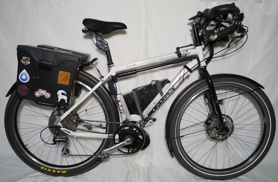
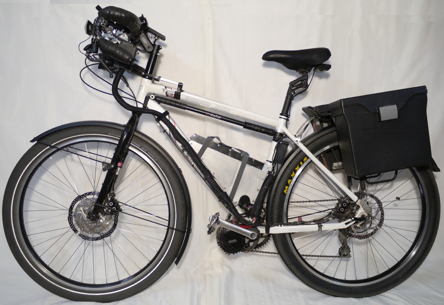
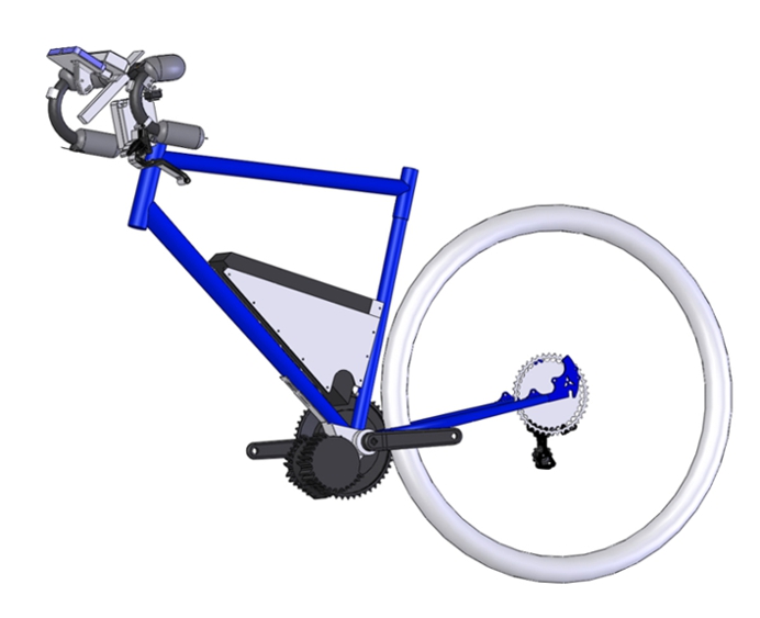
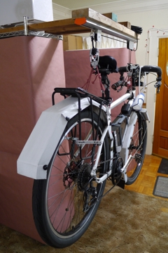
Ebike right and left view.
Donor bike: Diamondback Trace Dual Sport, Hybrid large 20", 68mm BB, 2013-2015. 700C wheels.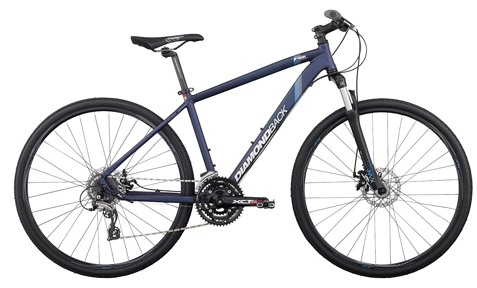
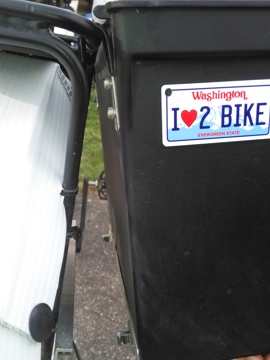
Name: 520 Bridge Tamer, Top speed: 38 MPH (Flat road, No wind, 125 RPM, 11T cog, 52 tooth chain ring, No accessories),
Range 56 Miles (Slightly conservative use of motor including hills of Seattle).
Weight: 60lb (with accessories). Accessories include all things that do not make it go forward: Back rack, panier(s), lights,
voltage converters, fenders,
steerstopper, man purse, and some tools.
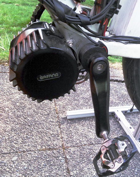
Commute one way: 14 miles, 32 min @ 5:30 AM, 43 min after 6:30 AM, weekdays except when roads are frozen, Length: 74", Bafang BBSHD 1000W.
Height: 47", Width: 18", Born: 1-1-2019, Maintenance log: 33,280 miles on 4/2/25.
Custom PAS_24 Spacer,Custom PAS_24 Cover FDM prints.
Chain Guide with Custom extension arm and spacer washer.
This Bafang motor is known by several names. Two different names on the Bafang web sites. BBSHD is not used on the Bafang
web site. Bafang web site only has this motor buried in their "OEM AREA". Links are not posted here as Bafang changes their
web site fairly often. Although the Bafang naming conventions has been stable for a while. Currently Bafang has this motor
listed as M615 and MM G320.750/1000.C. Although the picture on the MM G320.750/1000.C web page shows M615 model number.
However notice there is no model number shown in the pictures above. Perhaps the web site pictures are only CAD renderings.
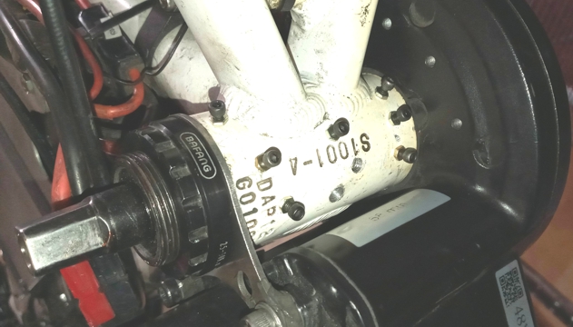
Also the motor in the pictures above is stamped with MM C320 100 09. Notice C not G as listed in the Bafang web site. All
this model /stamped numbering variants may be due to the motor being manufactured in many variants. 68mm, 100mm, and
120mm bottom bracket lengths and shipped in 750W and 1000W settings. Currently to view this motors web page navigate to
https://bafang-e.com/en/home/ choose OEM AREA choose COMPONENTS choose MOTOR use FILTER and choose mid motor.
Scroll down to MM G320.750/1000.C and finally to the actual web page. Be patient as all pages on the Bafang web site load slowly.
The M series may be an oldernaming convention and these web pages do not have as much information as the current route to
get to this motors web page.
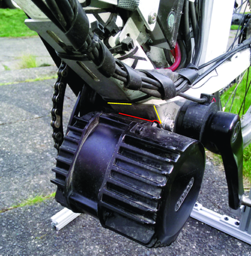
As the BBSHD is an insert and not threaded into the bottom bracket there will be some gap between the bottom bracket and
the motor shaft housing. The gap can cause the system to wobble especially while pedaling with high torque / high RPM. The
BBSHD produces a lot of torque that can add to the wobble problem. If the wobble problem is not dealt with besides not being
able to pedal accurately, galling and wear on the somewhat fragile threads of the bottom bracket can occur adding to the
wobble problem. The motor spindle housing must be stabilized using a combination of means. The BBSHD lock ring stabilizer
that comes with the BBSHD is not recommended as failure caused by too much torque can damage the surface of the bottom
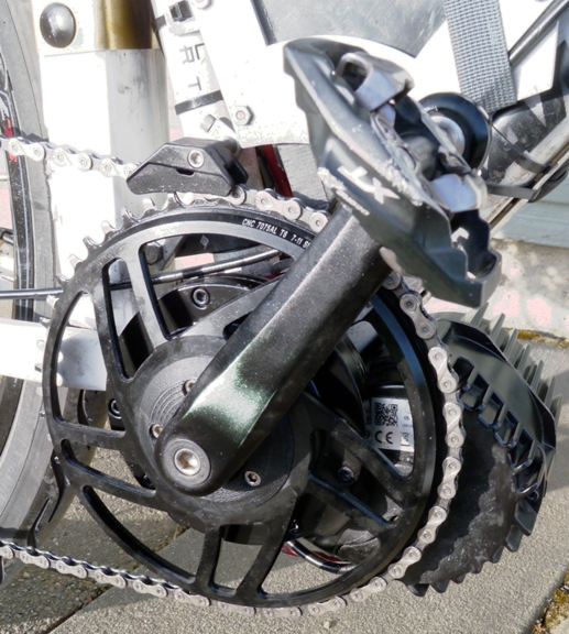
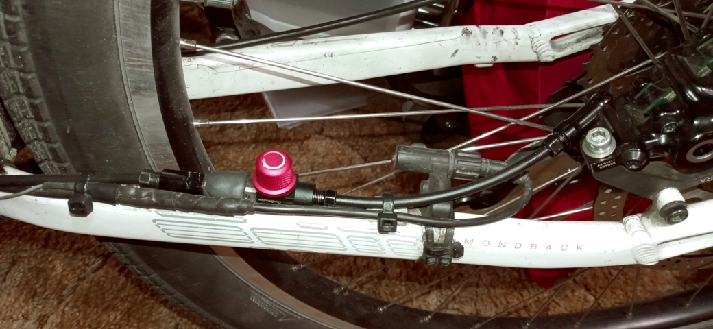
bracket with the teeth of the BAFANG stabilizer. The common third party stabilizer is shown above. A straight arm version is
available also. These two stabilizing bars handle the torque well, however they do not address the gap / wobble problem
well. Carefully placed shim strips will help the wobble problem only so much. To stabilize the motor shaft housing fully a
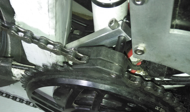
stabilizer bar and the "Frankenstein" is the most positive motor spindle stabilization technique as shown below. Drill and
tap holes for small fasteners to contact the motor spindle housing and push the motor spindle housing against the bottom
bracket creating three point contact on each end of the bottom bracket plus one in the center for good measure.
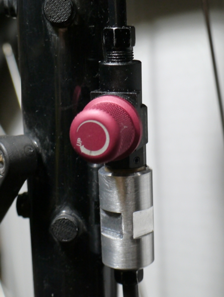
A stabilizer bar model BSBF-1 is sold by California Ebike and resold by Luna Cycles will require some modifications of
bending and or grinding with a rotary tool for proper fitting. The process of fitting will require several inserts and
refitting of the motor to get it right and take ~35 minutes. Assure the ends of the bottom bracket are clear of paint, flat,
and perpendicular to the bottom bracket. A hand electric rotary tool and rasp bit will aid in grinding the stabilizer bar
especially around the curved motor bolt boss area shown in red. Use caution to not grind too much per refitting, as forming
will change areas needing grinding. And the zone between the motor and frame may get too narrow. This particular stabilizer
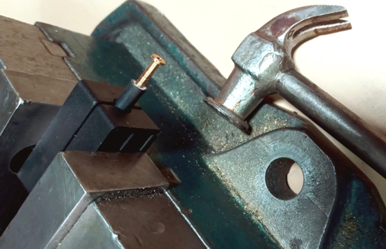
bar allows getting the motor closer to the down tube of the frame with the bend on the tine of the stabilizer bar. A large
vice will aid in forming a sharper corner at 2 places marked in yellow. An adjustable strap may be used to hold the motor
fairly close to its final installation angle during stabilizer bar refit and a final installation. Assemble the stabilizer
bar, the first motor lock ring, and the two motor fasteners after inserting the motor spindle housing into the bottom
bracket. Spacers may be needed between the stabilizer bar and the motor at the two motor fasteners. Assure the two motor
mount fasteners and spacers are the correct length to not strip motor mount threads and or bottom out the two motor mount
fasteners. 1/4" zip ties can be used to secure the stabilizer bar tine to the frame, two at the cutaway section of the tine
and two closer to the motor. Some softer plastic cut to the shape of the tine and placed between the tine and the frame may
mitigate marring the frame in this area. Adjust stabilizer bar motor angle bend to account for plastic shim.
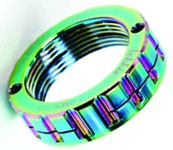
BBSHD is supplied with a spindle body lock nut with four notches to tighten the nut. A wrench to use on the four notches has
the fingers of the notches in the same plane as the handle. This makes finding a good ergonomic position to apply torque to
the wrench without the wrench interfering with the frame difficult. Would have been much better to have fingers 30 degrees
offset from wrench handle. A locknut with teeth to match the other side of the wrench (the side meant for BAFANG jam nut)
was tried. Although the new lock nut was tightened easily with correct ergonomics, the locknut was found to back off during
usage. The original BAFANG locknut with related jam nut was returned to use.
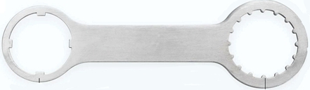
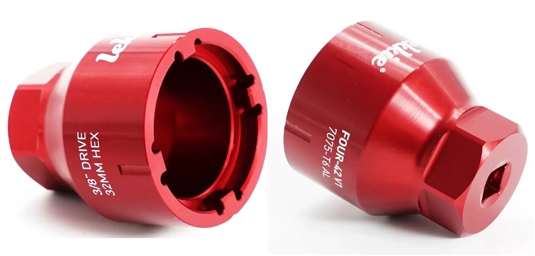
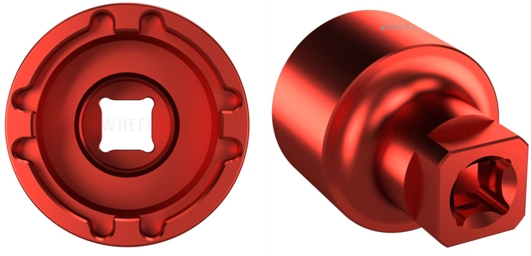
Better tools for removing and tightening the lock nut include these types of tools. Likkie available at
California Ebike,
E-BIKESOCKET07 exclusively manufacturesd and available at
Wheels Manufacturing.
Both companies are worth
viewing their entire offerings.
This effort and attention to detail will help keep the motor spindle housing stabilized and free from creaking noises that
can sometimes be confused with crank arm creaking noise or motor noise. Before installing crank arms removing paint or
varnish from the JIS square taper area of the motor spindle will aid in reducing crank arm creaking noise. Use of
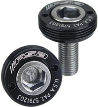
FSA Self-extracting crank bolts, JIS-M8
to act as jam nuts for the crank arm bolt will aid in keeping crank bolt from backing
out and crank arm from getting loose on the motor spindle causing crank arm creaking noise. Do not use the self extracting
feature to remove the crank arm if possible as threads of self extractor are somewhat fragile. Best to address these noises
before they can start so that if noises should start to emit from the motor / bottom bracket / crank arms area they can be
more easily identified. A tool was made to tighten the FSA-Self-extracting-crank-bolts-JIS-M8. Pins 0.091" diameter, 0.659"
apart. Pins can be made from drill bits. Keep pins short to avoid breaking. Body should be flush to Self extracting bolt jam
nut. Park freewheel tool will not deliver enough torque and strip FSA self extracting bolt jam nut holes. Harbor Freight
Adjustable Pin Spanner Wrench is too big.
While indexed 8 speed bar end shift levers were used initially, indexed shift levers were not accurate across all the
gears causing"skipping" or the tendency of the chain to switch gears momentarily followed by bad noise. An Archer
Components electronic shifting system was installed and shifting performance was improved dramatically. This system
allowed use of the existing, well working, and economical Acera derailleur. unfortunately this system failed mechanically
and shortly after unfortunately Archer Conponents went out of business. An L-TWOO electronic shifting system
was
installed. Unfortunately this system also failed due to shift lever BTLE loosing pairing. Getting pairing instructions from
Aliexpress seller took 1 month. The LTWOO system is working now. Although logging in requires 2FA and LTWOO code
never gets sent. Making the LTWOO shifter power from ebike battery may require dismantling an existing battery
and using the shell for power input. Both systems can be controlled and adjusted from their respective apps. SRAM
and Shimano integrated derailleurs do not have individual cog adjustment like the two brands mentioned. A NEMA 8
stepper motor with integrated lead screw did not have enough power to shift the derailleur. A NEMA 11 stepper
motor with integrated linear actuator will be tested.
The Grin Technologies PAS_24
is a modified version of the King Meter
Mini Sensor II for use with Grin Technologies Cycle
Analyst V3. The PAS_24 will update the Cycle Analyst more often due to 24 pole quadrature output than a single magnet
sensor for more accurate RPM display. The PAS_24 was designed to work with hub drive systems and interferes with the
BBSHD motor, so it must be heavily modified to integrate with the mid drive motors. The tine must be cut off. The collar
of the PAS_24 does not easily fit onto the JIS standardcrank shaft. The funny shape of the collar needs to be reworked.
There is no good way to stabilize the funny collar under rework. The collar and associated magnet ring must be removed from
PAS_24 for the rework operation. This will destroy a portion of the front side of the PAS_24. Attach the sensor portion of
the PAS_24 in place with thin double sided tape. A special ring must be designed and fabricated (printed) to space the
collar and magnet ring from the BBSHD insert surface to get back in line with what is left of the PAS_24 quadrature sensor.
Then a cover must be designed and fabricated (printed) to protect the PAS_24 sensor and magnet ring from the harsh
environment around the bottom bracket area. PAS_24 is inexpensive, buy two if you are concerned about messing the first
one up. Good luck and Godspeed. Direct RPM reading will allow optimal ebike performance.
Derailleur: Rear, 8 Speed, Shimano, Acera M360. Microshift has an 8 speed derailleur and bar end shifters compatibile with Shimano Road and MTB 8 speed system.
Cassette, 11-40, 8 speed: ZTTO 11, 13, 16, 20, 24, 28, 34, 40 or
Sun Race
11, 13, 15, 18, 22, 28, 34, 40. Best to reuse steel cassette lock ring than to use ZTTO Aluminum cassette lock ring.
Pedals: Shimano PD-M785 SPD.
Custom Chainring Spacer FDM print 0.10 (compresses to .07").
Chain guide: Origin8, Torqlite UL or
Problem Solvers, Chain Spy.
Because of battery location a custom arm was added between seat tube adapter and guide.
A 0.042" 1.08mm washer was placed between the halves of the chain guide for correct 7 speed operation. No more chain drop, YEA!!
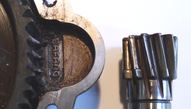
Below pictures show a new chain ring and a chain ring after 6000 miles. Notice burr on back side of chain ring while front
side of chain ring did not have a burr. No reviews mentioned Narrow Wide wear with burr. Unknown why burr was on inside
of chain ring only. Always shift to the lowest gear when approaching a stop when using a 52T chain ring.
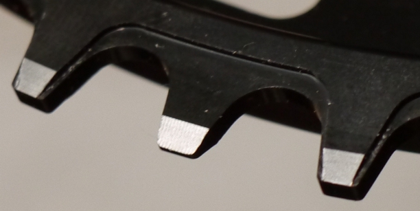
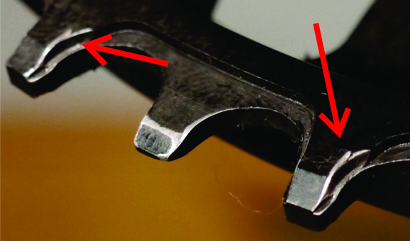
Inside view of New Narrow Wide chain ring. Same view after 6000 miles.
Chain "skip" on cassette can manifest in two ways, however may be caused by a few factors. Normal
humans and some athletes can produce upward of ~ 400 watts of power while some motors can produce
1K watt or more. The higher the wattage applied from both non-motorized and motorized systems the more
all components must be accurate. This is why there may be less noticeable "skip" with human powered
systems as opposed to motorized mid-drive systems. Chain "skip" is a phrase and is usually not what
is happening. Except on the smallest cog in a high torque system, where the 11T cog does not have
enough chain wrap causing chain jump and chain trying to resettle or cassette is new and chain is old.
Factors causing "skip" are usually the action of the chain shifting onto the next smaller cog
momentarily and shifting back to where it is supposed to be. This shifting can be caused by the following.
Indexed shifting levers may not be linear across all cogs of a cassette caused by the casting process or
inaccuracies of the shift lever cam. Cassettes may not have perfectly spaced or parallel cogs. This can
be caused by the spacers between the cogs or non planer cogs. Most cogs are mostly stamped parts that
may have slight warpage due to the stamping process. Spacers are sometimes plastic for cost and weight
injection process can produce slightly irregular dimensions and or non planer parts. Stamped metal
considerations. Plastic spacers can have the similar issues as plastic spacers. Machined spacers or
machined webbed cassette body construction may mitigate these issues however may be higher cost.
Chain quality and type are important. High torque systems will shorten the life span of chain and
cassette. Shifting in a hilly urban setting will shorten the life span of a derailleur. Derailleur
adjustment is critical especially with high torque, and considering derailleur pin / idler pully wear.
Derailleur idler pullys are notoriously loose and can be replaced with quality types with deep valley idler pulleys .

A 46T chain ring and an 11-32 cassette combination was installed initially, however BBSHD has enough
torque to drive a 52T chain ring and 11 - 40 cassette combination with 11T cog locked out via
derailleur adjustment. 7 speed operation delivered high speed, and is granular enough for ebike.
Several brands of cassette models were tested.
KMC X8 chain available at
Aliexpress and ZTTO 11-40 cassette
also available at Aliexpress work well together. Change these parts together. Mushroomed chain
rivets are recommened for high Nm / wattage motor use. Flat end rivets are not recommended. Finding
chain and cassett work better toward end of life as measured with tools like Park Tool Chain Checker CC-2 or
less expensive similar products
available at Aliexpress. Do not force gauges onto chain. If gauge does not fit
on chain the chain needs to be worn in a bit. New chain reads ~25% and was allowed to stretch to 100%. Almost
1200 miles measured using this combination of chain and cassette. Purchase chains and cassettes in bulk,
do not waste money on shiny parts for ebike. Be nice to new chain for at least 100 miles. Best to remove
factory lubricant with WD-40 or equivalent; wipe dry, and lubricate. Bridge Tamer chain length is 62" including master
links. Two master link sets and a short section of chain are needed as chains come precut to 58". This length
allows for derailleur arm to be slightly forward in low gear. Aids in less chain bounce during high (>88) RPM.
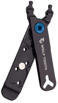
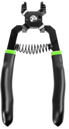
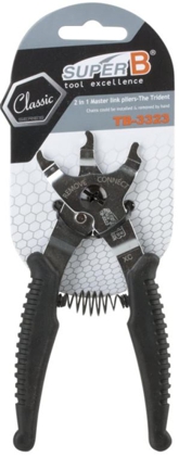
Small chain tools do not develop enough leverage to remove or set master links consistently. Right angle chain
tool tends to bend chain in a bad way. Super B has exelent performance and light enought for tool kit.
Super B on Amazon and
Aliexpress.

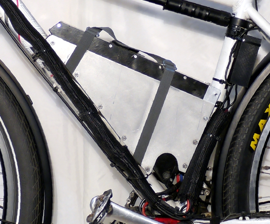
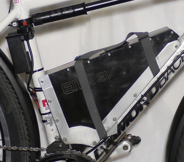
Custom battery holder for
EM3ev 52V triangle 14S6P with a DC DC Converter set to +5VDC for charging USB accessories behind seat tube. This battery
came with a battery bag to velcro onto a frame. It places the battery with a much higher center of gravity, and a rider will rub against it enough to be anoying.
Best to make a holder. Battery pack holder cut out area allows clearance for pack removal. Holder materials: Hardware store T extrusion, Aluminum sheet,
6- 32 threaded rod, nuts. This holder can be adapted to most bicycle frames. Bafang motor kits are usually purchased from the company selling or
manufacturing the battery pack.
Battery pack manufacturing takes some fairly attainable knowledge, some semi expensive tools to do it right, and some very expensive tools if you are
actually going to test them. Then there is obtaining a relatively small quantity of the right chemistry of batteries cost effectively. Unless you are an avid
experimenter best to buy a pack from known reputable manufacturers. When the packs are dead do not try to fix it unless you are a true experimenter
with experience in pack assembly. Best to dispose of the pack correctly, and get a replacement from the original battery seller.See this
or this.
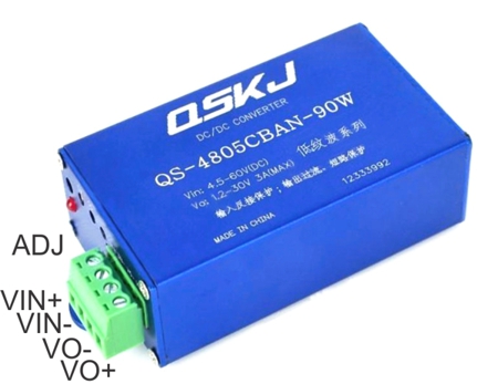
Two variable DC converters for general purpose +5V and Archer shifter +12. Manufacturer: QSJK, Pn: QS-4805CBAN-90W.
(Currently on ALiExpress only). This variable converter is potted in a nice blue aluminum housing
to help maintain a lower temperature.
and a detachable green connector with compression screw terminals. Other PCBA power supplies were tested and found too difficult to
heat sink. The case ears can be easily removed (small screws) for the converter to fit in the power supply holders on back of the seat tube
for environmental protection.
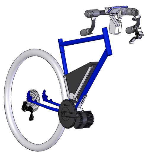
CAD models of BBSHD IGS STP STL
SLDPRT, battery, and chain ring measured on granite table with precision measuring equipment.
If you need models of BBSHD, custom battery holder, or PAS_24 spacer and cover printed please use contact at bottom of page.
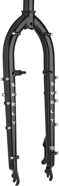
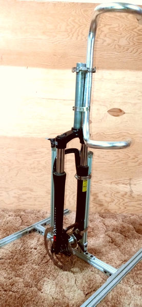
Fork, Head Set, and Stem Replacement: Surly Ogre, Axle to Crown Length: 447 mm, Brake Mount:
Removable cantilever studs, 51mm IS Disc Brake mount,
Front Axle: 9mm x 100mm, Material: Chromalloy Steel, Offset: 43 mm, Steerer Type: Straight 1-1/8-inch, Wheel Size: 29-inch, 27.5+, Powder coat finish: Black.
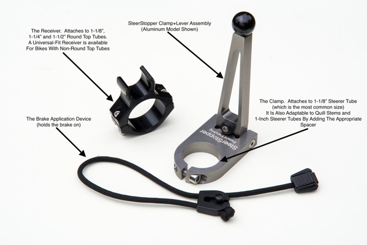
STEERSTOPPER Steering holder (Recommended for stabilizing bike during times not on bike seat, loading, and maintenance)
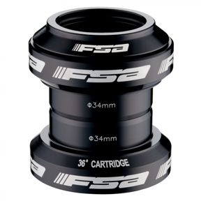
FSA Orbit MX Head Set 36 Degree Cartridge
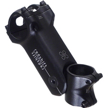
Redshift ShockStop Suspension Stem (with graduated durometer inserts
of default orange 50 and blue 60 durometer)
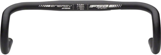
FSA ENERGY TRADITIONAL ALLOY HANDLEBAR RD-201TN 420mm is getting hard to find, 400mm and 440mm is less expensive.
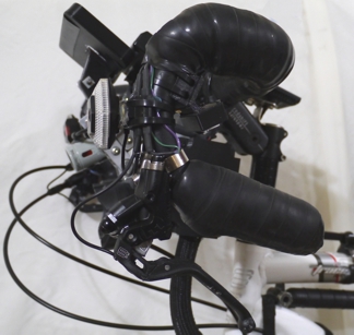
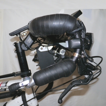
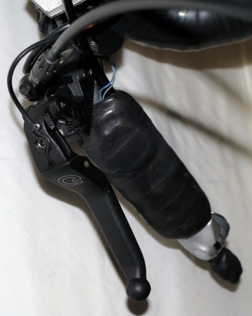
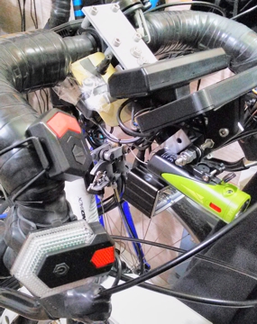
Top left view highlights the left front turn signal, a Magura MT5E brake lever, and a side view of the custom PAS switches, and a
Redshift ShockStop Suspension Stem.
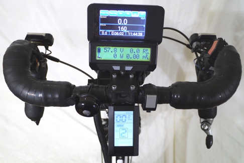
Top center view shows the Bafang display C965, Cycle Analyst V3,
a dedicated cell phone (Android, no SIM chip) with
IPBike app, an Incredibell bell,
a front light switch (gray), and turn signal switches (red), and a Shimano 8 speed bar end shifter. Between the C965 display and the Cycle Analyst is
a custom mounting plate and stand offs (stand offs because of a flat plate above round stem) mounted to the ShockStop Suspension Stem. Mounted
to the custom mounting plate is
T-Slotted Framing. The T-Slotted Framing secures holding brackets for the Cycle Analyst, cell phone, junction box,
and light system. The C965 display is mounted to a Steer tube Mount
via a small custom adapter plate.
At 14,700 miles the entire electrical system was upgraded and a wider handlebar (listed above) was installed. The original
electrical system, while working fine, was not optimal. A junction box was designed and 3D printed to contain a system PCBA,
switches for Motor On, Cycle Analyst, system charging / USB, and throttle resistor networks. The upgrade allowed better
wire harness routing with good trouble shooting accessibility, and included a single power supply mounting, and a "3000lm"
high voltage front light
and bracket. This light working directly from the main battery eliminates a need for a specific voltage
power supply. The light needed some modification to make it mechanically stable, and is worth the effort for a very bright
and inexpensive torch. A NiteRider Lumina 1200 Boost
spot light with Lumina Adapter Mount
was added to help spot
sunken utility vaults and places with bad road surface.
The Motor On switch replaces the middle switch of OEM tri-switch. This was done to mitigate accidentally entering the system area of the display
or turning the motor off while trying to control PAS levels at higher speeds. PAS is now controlled by the custom 2 switch assembly. This assembly
is placed to allow the left hand knuckles to contact the PAS switches accurately (while using drops of the handle bar).
The throttle input membrane switch (ergonomically positioned at left thumb while using drops of the handle bar) replaces a twist or thumb throttle.
Using the throttle switch sends wide open throttle signal to the motor. Using PAS is adequate for most riding. Working through the PAS levels first
to get up to speed before using the throttle switch on pavement with good surface and roads of good conditions provides optimal riding.
Membrane brake switches are conveniently positioned at left 1st finger position while using drops of the handle bar and at left thumb position while
using tops of the handle bar. These switches along with brake lever and motor cutoff switches will aid in stopping and especially shifting as
mentioned below. Membrane brake switches mounted on the levers of the bar end shifter did not work well due to the action of applying pressure
to the switch and rotating the shift lever at the same time as the combination of forces would not allow the indexed shifter to settle properly.
Membrane walk fast switch is installed at right thumb while using drops of the handle bar. Walk can be achieved on BBSHD via holding the down
PAS switch until P on display indicated activation, and will stop after release of down PAS button. BBSHD P walk speed is fairly slow, however
good in situations of extreme angles such as loading ramps. Membrane walk fast switch is set (through resistor network in the junction box, see
schematic below) to allow a normal walking pace, especially while walking up hill.
BBSHD display inputs the PAS and motor on switches, displays PAS amount, and battery level. BBSHD display battery indicator is set for a
specific battery chemistry (usually for slightly lower voltage chemistry) and may not indicate higher voltages but always indicate low levels
correctly. BBSHD motor inputs brake, throttle, speed sensors directly, and interfaces with display.
Cycle Analyst V3 inputs PAS24 pedal RPM (so nice to have cadence on a fast ebike), speed, battery voltage (for system input, digital and
graphic display, and brake sensors (used to stop cruise control). Cycle Analyst V3 inputs throttle for and cruise control and has output
to throttle signal. Jumpers in junction box can disable cruise control. Cycle Analyst V3 displays voltage, watts, crank RPM, speed, brake
and throttle indicators. Cycle Analyst V3 voltage indicator is accurate however the battery level graphic chemistry setting does not have
all battery chemistries. So graphic may not indicate well for batteries that have lower operating range. However digital read out is always
accurate. BBSHD display and Cycle Analyst battery graphics do track in respective ranges.
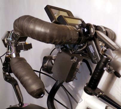
Top right view includes a turn signal, main motor cut off rocker switch (motor cycle style) conveniently located inside center of drop handle
bar, MT5E brake lever, and a Shimano 8 speed indexed bar end shifter rotated to and ergonomical position for the hand to have greatest
leverage.
Second row left view shows custom BBSHD PAS 2 switch assembly conveniently located inside center of the left side of drop bar and the
junction box with switches. A Steerstopper is near the frame (great for loading items on ebike, loaeding ebike into transit, and maintence.
Metal version recommended.
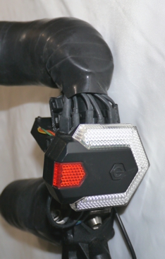
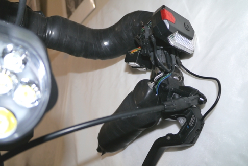
Second row center and right views highlight motor cut off membrane switch placements. Silicone Nano tape (thick) was used for handle bar
padding, and wrapped with black silicone repair tape. The silicone repair tape leads over membrane switches and covers well. The
Nano tape and silicone repair tape covering provide a supple and durrable padded handle bar wrap.
Bottom view shows location of walk fast switch.
Motor should receive off signal from brake levers, membrane switches, or motor cut off switch before shifting starts to avoid jamming gears and or a loud
report during shifting. Off signal should last for at least 2 pedal revolutions after shifting, and assure chain is engaged correctly before releasing motor off
signal switches. Motor off signals from momentary membrane switches work well for shifting while keeping bicycle momentum without having to use brake
lever motor off signals. A toggle switch is recommended to use before stopping to allow controlled braking and shifting down at the same time without
concern for accidental motor start. Use the main motor toggle motor off signal switch religiously, always before dismounting from seat, for good safety.
Keep in mind motor does not do any actual braking before it stop. Motor simply turns off and slows down until it stops while bike is still moving.
The MT5E lever internal switch actuates early in lever travel, and contact actuation can be lightly felt. Unknown if the contacts are magnetically or
mechanically actuated. Assure "closer" normally open model lever is used with BBSHD motor.
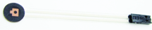
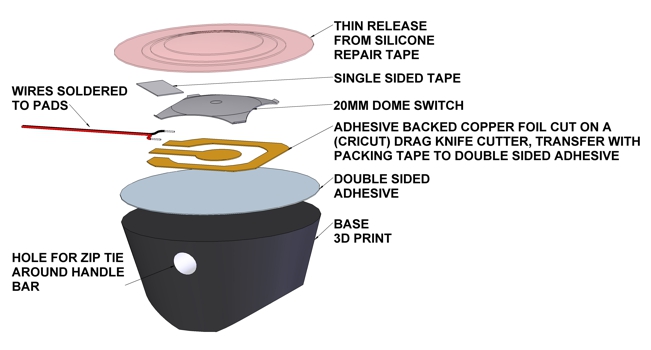
A membrane switch pictured below (available from many sellers on eBay) was tried and was found to be too small when wearing thick gloves for good
tactile response. A custom switch was designed and fabricated. This switch works well in all conditions, has good seal, and wires are easier to route
without constraint from original membrane switch flex circuit. When installing wrap one layer of silicone repair tape over center of switch, then finish
handle bar wrap overlapping the center tape a small amount so as to not have thick tape over center of switch. Apply repair tape as needed to mitigate
moisture egress, with connector accessible for connection. Switch is available from Protomatix.
Do not waste time with inline shift cable sensors. These sensors are momentary and do not react in time for proper shifting and allows the motor to start
before shifting is completed. When multiple brake lever, membrane, and toggle switches are used include individual plug connections for troubleshooting
allowing isolation of stuck motor off signal in the rain or cold. All motor signal off switches are connected in parallel. Use
breadboard jumpers to connect to
switch. Make connector of switch and dual board jumpers moisture resistant with heat shrink and hot glue back fill. Connect switch to dual breadboard
connector. Use electrical tape to cover heat shrink of both dual connector ends of all connections with two wraps. Creative engineering will be required.
Drop bars are wrapped with several layers of
Nano Tape and finished with
Silicone Repair Tape (self-fusing) for good good cushion and abrasion resistant
finish. Tip: Do not wrap Nano Tape, lay it in line with handle bars in pieces. Measure diameter with thumb and first finger. Bias layers toward palm of hand.
This will take a while. Labor of love. Finally wrap with Repair Tape.
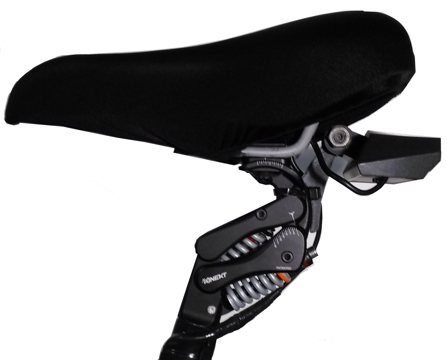
Seating:
Seat post: Cirrus cycles, Kinekt (Body Float). 1 each spring included kit Purple 100-150 lbs., Black 150-200 lbs. default,
changed to Orange 200-250 lbs. Change bottom spring only. Some getting accustomed to, great to ride on.
Seat: Sella Royal, Respiro Athletic Gel or Serfas Dual Density with Cutout Seat cover recommended.
Light: Ampulla rear with direction indicators, ground laser pointers. Light did not allow running and charging at the same time.
Work around: Remove internal battery,
add small slide switch to battery cover. Connect +5VDC to battery cover switch. Connect switch to LM317 (or equivalent) TO-220 package regulator circuit. Connect
+3.7VDC output to where battery was. Short PCB light switch. Now light does not turn off while riding. Light Bracket: Rear, Custom (FDM print).
Wheels:
Velocity rims and Hubs American made (YEA!!).
Rims: Cliffhanger 4000M-62236, Black, 700c, 36h.
Front Hub ATB Disc 36h Black, h06-36.
Rear Hub ATB 135mm h149-36.
Spokes: Sapim spoke length in millimeter, FL and RL 287, RR 286, FR 289
Brakes:
Magura MT5E "Closer" Normally Open Levers, Quad Piston Calipers
Kit.
QM-5 Front and QM-9 Rear IS caliper mounts for 203mm rotors.
90 Degree and
40 Degree "Banjo"
Tube Adapters. Ti Cycles hydraulic brake line coupler. Outbraker
Dial adjust, kit of 2, assure to choose
correct style.
Unfortunately Trickystuff drop Bar MT lever adapters sold on Shapeways Store is not available any more as Shapeways
has changed. SRAM SLRS0026 Lever Clamp
kit.
Rotors and brake pads in last part of brakes section.
Magura bleed kit including nipple Installer.
Front and rear cable disk brakes were tried, including a disc plus rim braking system in front. Overall braking performance was not
optimal for heavy ebike especially on wet days, and rim brake were hard on the front rim. Rims and pads required constant maintenance.
Cable operated disc calipers are not as powerful as hydraulic brakes. Cable brakes can be adjusted easier than hydraulic brakes with the
convenient cable adjustment nut for quick action, providing the wheel is true. Due to hydraulic brake atmospheric pressure bleed, calipers
bite midway through lever travel. Using the Outbraker greatly enhances hydraulic disc brake caliper adjustment. Hydraulic quad piston
calipers greatly increases stopping power especially on wet days. Know your personal and your bikes braking capability.
All MT levers have 7/8" diameter clamp for MT handle bars, while drop bars are 15/16" diameter. Most MT lever clamps have a wide clamp
using a hinge or fixed C which will not work on the round part of drop bars. Magura MT levers use a two bolt mounting system which allows
use of the lever mounting adapter for drop bars. The adapters also make levers easy to remove with center bolt for bleeding the hydraulic
brake system. The SRAM SLRS0026 Shifter Clamps must be used as standard drop bar lever clamps are too big to fit in the adapter area.
Magura brake kits arrive preassembled with a straight exit lever jam nut and a swaged 90 degree banjo at caliper end of hose, and filled
with "Royal blood" mineral oil. The installation will require draining the oil, refilling the oil after assembly, and "bleeding" the system
while removing air bubbles. This is a gravity dependent task. Plan work ahead to avoid excessive oil spill. Mineral oil is not as hazardous
as DOT brake fluid, however PPE should be used. Fixturing helps mitigate oil spill. Wise to have one 40 and two 90 degree banjos on hand
for this installation. Also 7' Shimano BH59 brake hose and 4 sets of compression fittings "olives" and nipples. Shimano BH59 with associated
nipples and olives seats well in Magura MT products. Shimano hose and Magura 90 degree banjo is less expensive than replacement Magura
hose with swaged banjo, readily available in bulk from good local bike shops or Ali Express, and more versatile. Banjos can be reused. Do
not use Magura olive with Shimano nipple or vice versa. Remove all brake pads from the calipers before proceeding to the next sections.
If pads are exposed to mineral oil they are done. Even if pad material is sanded pads will develop glaze and or squeak almost immediately
during a short ride. There are two threads for jam nuts. One for MT lever, and one for banjos. Thread specifics listed below. Use open
end wrench on banjos and jam nuts when removing and securing jam nuts.
Drain brake systems using the following steps. Place a small clean container to capture the oil in some type of clamp, vice, or holding
fixture on the floor. Place tape, rubber bands, or some implement near the small container ready to hold the hose in the container when
removed from lever. Place the caliper in a holding fixture on a work bench with plug screw facing up and banjo down. Hold lever above
caliper. Unscrew lever jam nut. Set lever on a shop towel while oil stored in master cylinder drains. Hold thumb over hose end, bring hose
to container, remove thumb, and immediately place hose in container. Place hose holding implement on hose. Mineral oil will begin to drain
into container. Remove button head plug opposite of banjo from caliper. Remove caliper from fixture. Hold caliper up and rotate around
to assure most of the oil is captured in the container. Remove hose from hose holding implement. Wipe oil from components and clean oil
spills. Remove swaged banjo from caliper, coil hose with banjo and lever jam nut, bag, store for backup.
Assemble brake lever components on the bike. Bridge Tamer uses a 40 degree banjo on the back brake lever, a 90 Degree banjo on the front
brake lever, and a second 90 degree banjo on the rear caliper for cleaner hose routing. 40 and 90 degree banjos help mitigate excessive
hose in front of bike with drop bars, as opposed to hose exiting straight out of levers. This task may take two of a 40 or 90 degree banjo.
Place smaller washer in banjo kit on banjo bolt. Place banjo washer in banjo groove. Secure banjo bolt adapter in MT lever. Feed banjo
bolt through banjo. Fasten banjo bolt into adapter, do not secure banjo bolt. Do not loose banjo washers. Place hose in banjo
and see how it routes before cutting hose.
The Outbraker dial allows fine control of brake pad to rotor distance. This distance can be a small (0.018", a few hairs) to cause levers to not actuate pads properly in their
optimum working zone, especially on plush handlebars. Another advantage of incorporating Outbraker is when fixing a flat tire. The dial can be fully retracted to allow pads
to open wide for rotor insertion when wheel is replaced. The Outbraker acts like the cable adjust nut and the brake quick release used for wheel replacement in cable brakes.
Magura MT lever hose exit uses a 9mm X 1.25mm thread. Outbraker has the mating 9mm X 1.25mm thread on a convenient swivel piece for alignment, and an 8mm x 0.75mm
thread in the body for a compression nut. Banjos also have the 8mm x 0.75mm compression nut thread. Outbraker is made to fasten directly onto MT levers, and will not work
with banjos on the levers. A combination of Outbraker on banjo would cause a vulnerable assembly on drop bar bikes. Outbraker needs to be adapted with a machined coupler
or modified with epoxy to be integrated for in line use. Epoxy option connects Outbraker (MT brake lever side) to a TiCycles 5mm hose coupler using
PC7 a strong 2 part epoxy
cement that is not affected by mineral oil. The TiCycles coupler will need to be modified on one end intended for epoxy with 3 small and shallow lathed flat groves so the PC7
epoxy will hold Outbraker and hose coupler together well. Mold PC7 epoxy to ~5/8" diameter. Do not cover areas for tools with epoxy. A machined coupler version will need be
tapped with an 8mm x 0.75mm thread on one side for a compression nut and a tapped 9mm X 1.25mm thread on the other side for the Outbraker. Coupler design needs to
include a middle flat area on the compression nut side about 1/8" thick for a hose nipple to seat against with a small hole for oil to pass through. Protomatix sells a machined
coupler. Interesting that Schrader valve stem uses 8mm x 0.75mm thread.
Work on rear brake first. Temporarily attach Outbraker with coupler to frame where it will fit and be used conveniently. install rear caliper. Cut hose as needed for
good service loop to MT lever banjo with steering rotation and to reach Outbraker, and the other piece of hose to the brake calipers. Include distance for hose
inserted into fittings. Assure end of hose is cut flush, do not crush hose. Remove hose pieces. Install a nipple in one end of the hose for MT lever to Outbraker
by clamping hose between Magura "installer" hose clamps PN 0321239 held in a vice, tap nipples into hose with a small hammer. Assure nipple is flush to hose.
This end will be used for the Outbraker coupler. Do not compress olive for the Outbraker coupler in the coupler initially. Compress all olives onto nipples in a
banjo first to assure good compression and inspect all olive location on hoses after removing banjo. Compress an olive onto this hose at the nipple end. Remove
Outbraker with coupler from frame. Place a jam nut on hose in correct direction. Place this hose with compressed olive and nipple into Outbraker coupler or TiCycles
coupler and secure the jam nut in coupler. Use open end wrench to hold Outbraker coupler. Place plastic cover of MT lever on hose from Outbraker in correct direction.
Place jam nut on this hose in correct direction. Place an olive on this hose away from hose end. Install a nipple on open end of hose. Compress the olive on the nipple.
Install a nipple into one end of other hose. Compress an olive onto this hose nipple. Place two jam nuts onto hose in opposite directions for correct olive compression.
Place an olive onto hose and install a nipple on this end of hose. Compress the olive onto the nipple. Hoses will need to be realigned for best service loop after initially
compressing olives. Account for hose twist for final secure. This task may take a few tries. Assemble other piece of hose to rear caliper and Outbraker. Do not secure.
Thread hose from Outbraker to MT lever. Assemble this hose to MT lever banjo. Do not secure. Temporarily hold Outbraker to frame. Proceed to find the best angle
for the service loops and secure caliper, lever banjo, and Outbraker jam nuts. Assure Outbraker dial is pointing in the intended direction. Remove all including caliper
and lever as a single piece for filling and bleeding. The process is basically the same for front brake, with Outbraker on fork.
To fill and bleed brake system install brake system in a fixture with brake lever well above caliper, and "EBT" Bleed screw up.
Install an inexpensive set of
brake pads in calipers. keep these pads only for bleeding and adjustment while in fixture. The
idea is to get enough oil in system to allow Outbraker to be about half way "UP" or in when pads contact rotor with early lever
actuation and get air bubbles out. Assure Outbraker dial is all the way out or "down" according to dial. The fixture has shim
stock held on to rotor with c clamp. Assure rotor plus shim (if needed) are the same thickness as rotor on wheels. MAGURA
"EBT" Bleed screw is fragile, remove and secure bleed screw with Torx T5 bit and lightly finger tighten only. Do not use a bit
handle. Magura bleed kit has two syringes. The syringe tips fit snugly into brake lever EBT hole, and into hose with caliper
adapter. This process is all gravity dependent and relies on air bubbles rising up in a fluid. Remove plunger from one and
insert syringe tip into lever EBT hole. Call this one EBT syringe. Insert other syringe tip into hose with caliper adapter. Call
this one "filling" syringe.
Draw "Royal Blood" mineral oil from bottle into filling syringe almost full. All this oil will not be left on brake system.
Most is used to assure proper air bubble removal, and will be returned to bottle. Holding filling syringe with tip up remove
tube. Bleed air from syringe. balance filling syringe on plunger end with tip up.
Replace button head plug on caliper opposite of banjo with adapter end of hose. Finger tight only. Insert full filling syringe
tip into hose. Push oil into system until oil in EBT syringe becomes visible about a 1/2". Actuate brake lever a few times to
fill master cylinder. Fill system with a little more oil.
Remove caliper and rotate while tapping and filling slightly to assure all air bubbles rise to banjo. Fill system with a little
more oil. hold caliper to straighten out hose while maintaining upward direction of hose to lever. Tap Outbraker to release air
bubbles. Fill system with a little more oil. Place caliper onto rotor and fixture, and assemble caliper fasteners. Do not secure
fasteners. Actuate lever while filling system with oil a little more.
At this point syringe in hose and syringe in EBT hole should be about half full. Hold filling syringe with tip pointing down.
Draw a bit of oil from system. Some air bubbles may rise into hose. Assure all bubbles rise into syringe. Fill system with a
little more oil. Do not allow air in syringe to enter system.
Remove caliper from system once again. Hold caliper slight above EBT hole with plug hole up. Remove filling syringe with hose
and adapter from caliper while maintaining meniscus of oil at plug hole and without allowing air into system. Set filling
syringe on shop towel. Install caliper plug and secure. This process may take some practice.
Reinstall caliper on fixture. Do not secure fasteners. Wipe all free of oil. Empty remaining oil in filling syringe into bottle.
Cap bottle.
Plug EBT syringe top with hand and actuate brake lever so pads close as much as possible. Do not bend EBT syringe tip or let
EBT syringe fall out of hole while doing pad closure. Remove EBT syringe with oil in it. Place finger on tip while removing EBT
syringe to not let oil spill and go to waste. Pore remaining mineral oil in EBT syringe back into bottle. Cap bottle.
Install EBT bleed screw without introducing air finger tight only with T5 bit. Caliper may have to be raised slightly to get a
meniscus of oil in EBT hole during EBT bleed screw install. wipe all clean of oil. Actuate lever. Assure pads contact rotor.
Outbraker may need to be adjusted. Check for system oil leaks.
With correct actuation of pads and lever feel remove pads. Wipe all clear of oil. Remove caliper. wipe all clean of oil. Remove
lever. Wipe all clean of oil.
Install brake system on bike. Install new compatible pads. Test brakes. Adjust Outbraker as needed.
Do not feel bad if this bleed did not get expected results. Try bleed process again. Try removing shim. Try thinner sacrificial
pads. Measure sacrificial pads and new pads with caliper. A very small distance between pads and rotor makes all the difference.
Once a combination of rotor, shim, and pad thickness in fixture is found to work with bike rotors on bike bleeding will be repeatable.
Place zip ties around the frame (eyes if available) and hoses as needed and a tie near the Outbraker's hoses. Assure proper
"bed in" of hydraulic brake systems before hard use. Recommended system bed in procedure includes accelerating to 20 MPH,
bring bike to near stop, 30 - 50 times. Bedding in front and back brakes separately will assure even bed in, as doing both
brakes at the same time may cause insufficient bed in of rear brake due to weight shift to forward of moving bike. Brake
pad particles are actually embedding on to the rotor.
Choice of rotors and brake pads is dependent on many factors such as riding style / competence, availability, affordability, and
mechanical considerations. Bicycle Rumor has a great unbiased post from four manufacturers Hayes, Shimano, Magura, and TRP.
For the true rotor geek view Brake Rotor Design and Comparison using Finite Element Analysis: An Investigation in Topology
Optimization. Most manufacturers do not recommend to mix and match their components. Bridge Tamer has been a good test bed
finding optimal configurations of parts from multiple manufacturers to accomplish multiple criteria. Criteria included low clack /
/ noise / choppy feel, 203mm diameter and +2mm thick rotor for low warp / good heat dissipation, and good availability. Magura
MT5e brake kit included MDR-C 2mm thick rotors (with large cut outs) and two single piece dual pads. Using these pads prohibited
replacement without removing the wheel. The Magura 8.S and 8.P brake pads could be replaced without removing the wheel. Using
8.P or 8.S pads with the included MDR-C rotor caused the clack / noise / choppy feel on the heavy ebike especially going down
hill. A two piece rotor was found to have interference with the caliper in the MT5e kit. TRP-41 (E23) 2.3 mm thick rotor (with smaller
cross drilled holes) greatly reduced the clack / noise / choppy feel. 8.P and 8.S brake pads are relatively thin (not counting metal)
and found to wear quickly possibly due to specific composition. Most 3rd party brake pads are relatively thick and sintered. With
proper bleed using SOMMET brake pads and TRP-41 (E23) rotors in MT5e brake kit was found to be an optimal brake configuration
for a heavy ebike used for commuting with several large Seattle hills. TRP has discontinued TRP-41 (E23). A TRP
TR-17 / Dorado
HD-E710 with 2.3mm thick stainless steel single piece construction, fewer and larger cross drilled holes, and wavy outside
diameter replaced the TR-41. Funny that TR-17 can be found on Tektro-USA web site but not on trpcycling website while TRP
RS01E / R1 (similar to TRP-41 in thickness, diameter, and cross drilled holes) can only be found on trpcycling website but
not on Tektro-USA web site. TRP-17 is similar to Teyssor
(low $) rotor and many others.
Teyssor rotor works, but oxidizes
easily and has slightly more choppy feel. Independent pads allows for more even rotor and pad wear.
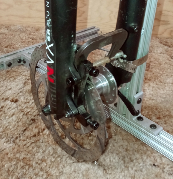
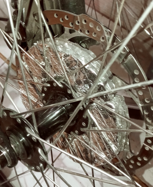
Magura calipers have magnets on pistons to hold pads in place during installation. Metal dust may collect in the pads area that
is slightly magnetized. Squeaking can develop when metal dust collects. Occasionally pull pads, sand pads lightly, clean rotor
with alcohol and dry with towel collecting dust and grit in holes and cut outs, and replace pads. Adjust caliper location by
loosening bolts connecting caliper to adapter. hold brake lever tight. Tighten each caliper adjustment gradually so calipers do
not walk during adjustment. Blowing calipers with compressed air may also help mitigate squeak. A front brake squeak noise
may be exacerbated by straight forks. Three layers of
Reflectix
insulation padding
held together with large sheet adhesive
applying light pressure between rotor spider area and spokes have reduced squeak significantly. Looks a little funny, no more
squeak unless pads actually need maintenance. Mitigating squeak can help reduce pad glaze.
Caliper pad to rotor distance can also be adjusted with shims made from
K&S Engineering 0.010" and 0.015" brass stock
available at good hardware and hobby stores. Insert shim between pads and pistons. Hydraulic calipers are "self-adjusting"
however readjusting caliper on bike is recommended for best performance. When using quad calipers and two shims best to
place shims on the same side of caliper. Third and fourth shims should be place on other side of caliper. Shims
are not as accurate as Outbraker, however are an easy alternative or when making pads last longer.
![]()
Tires, Tubes:
Rear tire was Specialized Electra, 51mm, 2",
Front tire was 700C Schwalbe, Big Apple, 59.7mm 2.35".
Both tires are now
MAXXIS Grifter TB96802000, 63.5mm, 2.5" with WTB THickSlick 29.
(Beads removed) inside Grifter for maximum puncture resistance.
Tube, Specialized, 29 X 1.75-2.4, 47-60 X 622, Full Metal Schrader Valve, D1 031E-1335
or generic 29 X 1.75-2.3 35mm full metal schrader valve
Fenders:
SKS BLUEMELS 75 U LONG. With best pricing
here. Two sets were purchased to use a rear fender on front for full coverage.
Fenders were changed from a fabricated version to more conventional fenders as they garnered too much attention.
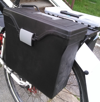
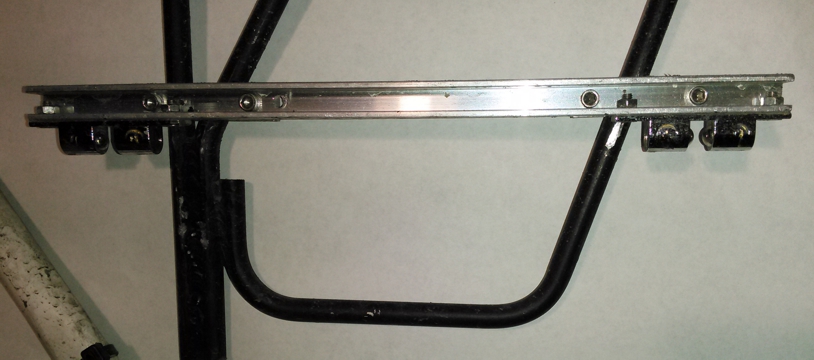
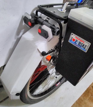
Carry:
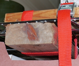
Jandd Mountaineering Expedition 29er rack. Jandd hooks (far right, zoom in if needed).
Perko #1222DP0CHR marine handle mounted on top of rack for e-Bike maneuvering.
Seadog #222823-1 marine door latches (2/ package, 2 sets needed, latches in middle picture, cleats in far right).
Iris portable hanging folder file boxes Letter X 6" (far left).
Latches are adjustable up and down via latch bracket (middle picture). Adjust so that hooks are snug to rack. Adjust latch tension with latch
side adjustment set screws so that boxes do not unlatch easily.
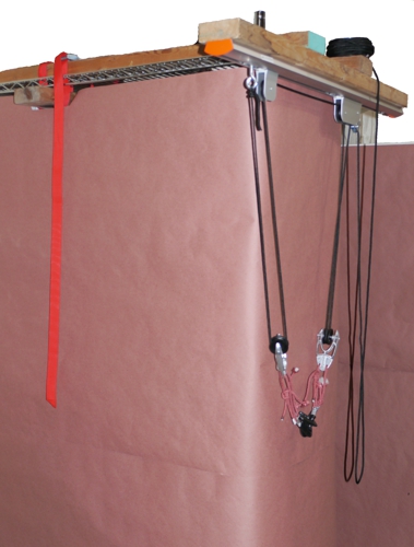
RAD Sportz
Bicycle Hoist:
A bit underrated for heavy ebike use. Not really intended for maintenance use, however it does work. The pinch latch is under heavy stress. The mounting
structure (wood) is also under some stress. Best practice is to use one hand to help lift and control the bike (to ease stress on the mounting structure
and pulleys) while using the other hand to control the rope and pinch latch. Controlling the rope involves pulling or letting out the rope through the pinch
latch (depending on the direction of travel) and locking the rope with the pinch latch (slight pull outward). The process takes some practice. Lower or raise
the bike about 8" at a time for best control of the pinch latch. Hoist may pick up one end of the bike first depending on where hooks are placed. Lower
pulleys fall off of rope while hooking up some times (inconvenient, could have used a shrouded guide system). Rope stays on after tension is applied.
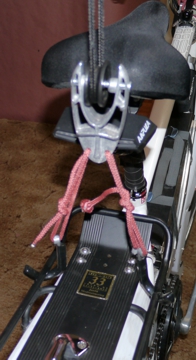
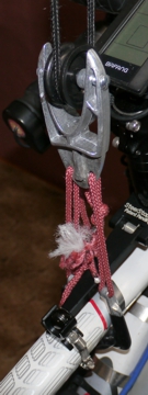
Replace hook bolts with small diameter rope for better hook versatility. System pulleys could use multiple wheel pulleys. Rope latch could be replaced
with marine cleat using cleat hitch techniques.
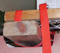
Hoist mounting 2" X 4" structure on wire rack put away. Hoist mounting unlocked.
Hoist mounting pulled out. Hoist mounting locked ready for use.
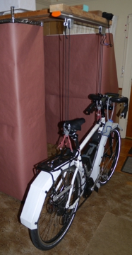
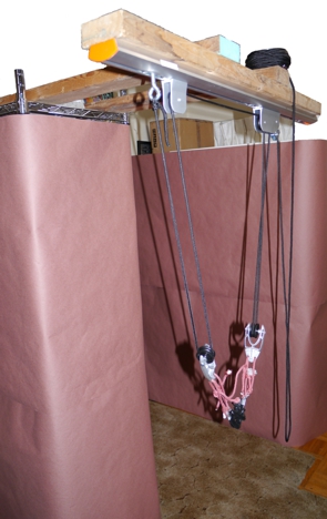
Bike on ground . Hoist hooks on rack.
Hoist hooks on frame. Bike in air.
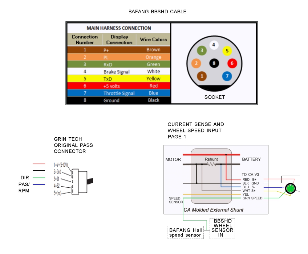
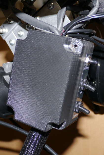
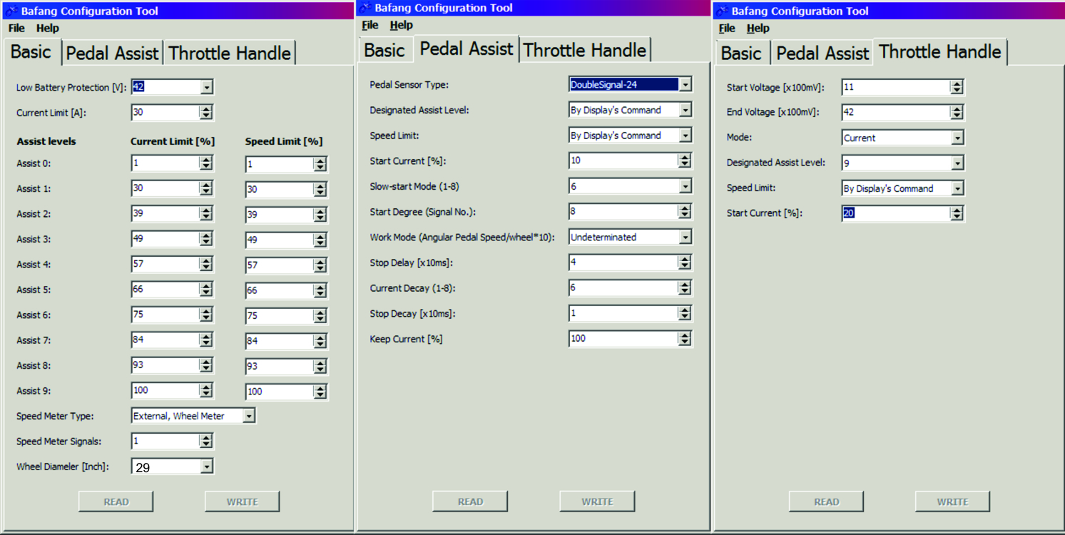
BBSHD setup:
Electrical schematic.
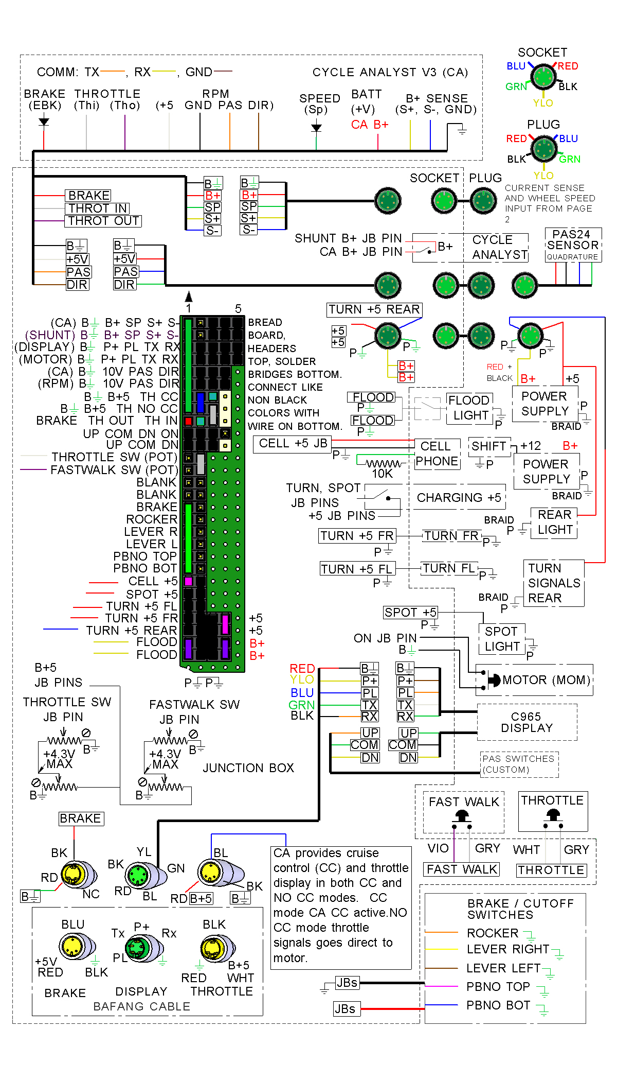
Custom junction box on drop handle bars includes moving PAS up/down center button to junction box,
Cycle Analyst power switch, +5VDC charging switch.
Configuration utility (Windows) shows current settings used for Bridge Tamer. There is discussion
of parameters meanings and settings
on
A Hackers Guide To Programming The BBS02 & BBSHD. This configuration allowed Bridge Tamer to easily achieve 34
mph on flat road
with good surface on a non windy day with no power drop out using 52 tooth chain ring and 14 tooth gear on cassett.
Settings can also be changed using EggRider or Speeed Configutation Tool.
EggRider display with buttons communicates with EggRider phone app via blue tooth.
App has ebike settings, speed display also with buttons, and graphs. EggRider display with buttons connects directly to the motor controller via the green 5 pin
connector on the main motor cable. Speeed is a stand alone app that communicates directly with the motor controller via the green 5 pin connector on the main
motor cable using a combination of a USB On The Go cable and a USB to serial programming cable with mating green 5 pin connector. Both can replace the
original Bafang display. However The buttons on the OEM Bafang display may be more ergonmic. Both will be easier to use for configuration than using
computer based configuration tools as they are more protable. Configuration is an iterative process. Change settings one at a time in smaller increments.
Ride the bike to get the new feel, Adjust again as necessary. After getting settings right the alternate displays were replaced with the OEM Bafang display.
Logic:
Build a bicycle that can fit on the bus bike racks in case of failure. Include suspension seat post and stem.
Plan was to use only Grin Technology Cycle Analyst V3 and remove Bafang C965 display.
Find out:
Frame and fork suspension is not needed on city streets and fork suspension will eventually give up on heavy ebike (use a lighter non-compensated fixed fork).
Minumum 2.5" tires are needed for crossing SR520 bridge with 37 expansion joint covers or EJC (1/2" thick X 4" plate, originally all with 45 degree edge chamfers).
2.5" tires do not fit on many bus racks and the battery must be removed to wrangle a heavy bike on to the bus rack.
Splash is serious at 18 - 43 MPH and serious fenders are a must and hook on bus rack will not work now so bus is permanently out.
Invest in AAA (they pick up bicycles and ebikes, actually used once so far, good service, get it, do not abuse it).
Bike could have been built on a fat tire bicycle frame but fat tires on fat tire bike frame actually take up most of the room where big fenders need to go.
An external circuit and CA parameter testing would be needed for CA use only and C965 PAS works fine plus walk mode is already working.
If you have bicycles toured you know your triceps are going to get a workout and same for ebike.
Walk Up Stairs for Windows Media Player
Walk Up Stairs for Quick Time
Rant:
D.O.T. Please take your class legal speak and keep your laws off my bike. With
a 60 lbs. bike, a 430' hill, 2 320' hills, some rolling hills, a windy 3 mile
long Bridge with 37 EJC, lunch, some tools, man purse, and a change of clothes
a 1000 watt mid drive motor is just about right. Get over it. W.S.D.O.T Will
the persons involved with the EJC decisions please get out of the gene pool.
About time most of those EJC got replaced. S.D.O.T. If the idea is to get more
people on bikes quit painting the roads and actually fix them. Bicycle lane
separators prevent street sweepers from doing the job in stupid bike lanes on
Eastlake Ave, 65 St, and Roosevelt Way. Have you noticed where the bike lanes
are most painted is often where the road is the most chewed up. The separators
often are placed right where the road is in better condition. Those lanes are
cute and dangerous at the same time, with plenty of trash. Watch out for those
share bikes, you might get taken out by a stray. Same for ebikers (new and
old) who don't have a clue about trail courtesy or awareness (put that phone
down and ride). Ebike manufacturers how about showing advertisements of real
commuters on often rainy days. Big fenders would become in vogue real fast. And
what is up with people wearing street clothes, are they trying make a fashion
statement or actually get some exercise? Is there anything wrong with clipless
pedals, drop bars, bicycle clothing and RPM on the display for better
efficiency?
Rant on flats:
Flats are no fun. I have swept 9020' X ~7' wide = 63140 square feet worth of glass and trash on Seattle streets, bike lanes, and trails that are on either my commute or my evening water front and park
ride. It goes deeper. Read Bike in Seattle, Glass and Trash, Bike Lanes, Homelessness, City of Seattle.
Safety:
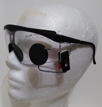
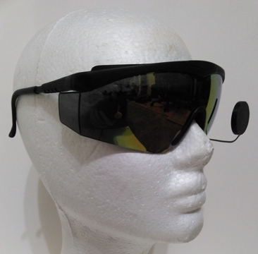
Always use eye protection when riding at any and especially high speeds day
and night. A mirror on safety glasses will help keep you alive. You must know
what is approaching, always be aware. Don't become a causality. Inexpensive
Cuda safety glasses or
Integra safety glasses(clear and tinted, available in bulk).
Using the same shape glasses will make transferring mirrorbetween glasses easier
to readjust. Protomatix sells mirrors shown, use contact below for information.
For added safety on fast ebike use bicycle turn signals rear and front with
Bluetooth remote control where letting go of handlebars to make hand
gestures is not an option. Purchase
$60 Amazon or
$31.31 Aliexpress
Motor Rebuild:
A good reference for motor rebuild is a set by Seb Z from ebikesforum and YouTube
Secondary cover removal 1/8, Motor core removal 2/8
, nylon gear plate removal 3/8, nylon gear removal 4/8,
nylon gear removal 5/8, nylon gear direction 6/8
, nylon gear mobil grease 28 and plate re-install 7/8,
motor core rotor install and re grease 8/8
At 7200 miles the BBSHD began to have a ticking sound every revolution. This sound could be
confused with other noises as mentioned above. Assure crank arm is attachment to JIS square
drive well and motor spindle housing is not shifting in the bottom bracket. Do maintenance here
first to eliminate these possibility.
The first maintenance cycle of that motor included a new pinion gear (sharp pinion gear teeth in the
engagement area), a pinion gear sealed 16003-2RS bearing with minor stiction, a secondary reduction
steel gear (three partially missing teeth), and the three pinion gear cover plate fasteners (changed to
internal hex counter sink fasteners for easier disassembly next maintenance cycle). Three maintenance
cycles per year is recommended to re-grease secondary steel gear and pinion gear for a high use ebike.
This lube is a fairly easy one. This would be an easier maintenance that can be done while motor is on
bicycle, and may increase life expectancy and decrease need for full bench maintenance.
The sound and feel started before total motor failure, there was ample warning. Listen to your motor
and know the feel of a properly operating motor. Wise to purchase a second motor, sparer motor parts,
an interface cable (octopus), and other related internal parts for good insurance on ebikes used for
dependable daily commuting. A spare motor allows for proper bench maintenance time. Many posts
mention the nylon gear or a controller failure. Bridge Tamer has never had a problem with these parts.
When rebuilding the motor core a new nylon gear may be prudent.
The difficult part of rebuilding the motor core is removing the silicone RTV on the three power wires
of the motor core attatched to the controller, the RPM sensor connectors, and the controller data
connector. Chisel and pick small pieces of silicone out cautiously, do not destroy connections.
Removing the three pinion gear cover plate fasteners may also be challanging because of Loctite
on threads of these fasteners and the use of phillips head countersink fasteners. Replacing these
fasteners with hex flat top fasteners may be prudent and aid in subsequent motor rebuilds. Assure
wires and connectors are back into the motor core pocket and not protruding from motor core at the
time reassembly.
The motor can be tested on a bench with a battery, an interface cable (octopus), and either a programming
cable or a cut section of a green 5 pin cable with P+ and PL wires exposed. Caution as there are many
manufactures of Bafang cables and wire color and connector shell diameter may vary. Only pin location is
standard. To turn the motor on connect P+ and PL. The programming cable has this connection already.
The motor will work with out a Bafang display or the program cable connected to a windows computer. A
computer is not needed at this time unless changing motor parameters. Using this setup will allow the
motor to run for a short time because speed sensor is not getting signal from wheel magnet. Enough
time to listen to the motor. Twisting the motor spindle by hand will start the motor. To test the motor
again disconnect the battery for ~5 seconds and reconnect the battery.The interface cable is sold on
various web sites with the 1T4 model number. Bafang web site has this model number referring to the
interface cable for their Ultra motors, which is a square not round connector at the motor end. Using
a display to turn on the motor is best practice as connecting P+ to PL can draw a fair amount of current
(small spark) momentairly. The interface cable connector at the motor end is not externally keyed. Use
caution to assure the arrows are lined up on both sides of this connection. Do not force this connection
to avoid bending connector pins. Although a certain amount of force will be necessary as this
connection is water resistant.
Was the motor worth rebuilding? Monetarily: Maybe a wash depending on how much your time is worth.
Ecologically: Yes less landfill, intrinsic value: Failure mode information gained. At least Bafang makes
a product that has some chance of being rebuilt successfully. Human made items will always break in
some way at some point of time.
At ~ 9800 miles the rebuilt motor began to make a different type of noise. A second dive into the motor did
not reveal much. A replaced pinion gear bearing did not fix the sound. The sound could be heard without
total reassembly. The pinion gear seemed to be the problem. The three new cover plate fasteners made
removal of the cover plate easier. Removing the pinion gear, grinding just a bit on the end of the pinion
gear, and taking a bit of edge off the teeth of the beveled area of the pinion gear relieved the sound.
Strange fix, sounded like a new motor. To be fair view the current mileage listed at the top of this page
with respect to the upper operating ranges (950W - ~1350W).
Credits:
Paul and the entire team from EM3ev
Erick Hicks and company at Luna Cycles
Doug Snyder and California Ebike
All the crew at R+E cycles
Wayne and staff at Greeg's Greenlake Cycle
Justin Lemire-Elmore with group at Grin Technology
Endless Sphere Electric Vehicle Forum
Bafang
Ifor Powell author of IPBike app
Tom, Alex, and team at Velocity USA
Surly Bikes
Sebz at Electric Bike Forum
Devin and Archer Components
 Protomatix